
 |
| Picture showing Diesel engines coupled to alternators |
Having learnt about electricity let's now take a look at what generates electricity - "GENERATOR". A generator is a device which converts mechanical energy into electric energy.
In a Generator a big coil of copper wire spins inside the Magnets ( This spinning is done by Diesel Generator or Prime Mover). As it spins, the magnetic field made by the magnets push and pull the electrons in the copper wire and as a result generate electricity. These moving electrons from copper wire flow into the power lines and these moving electrons are what are known as CURRENT. In other words we can say that Electric Current is a measure of the amount of electrical charge transferred per unit time. It is represented in Amperes which means coulomb/sec.
HOW DOES A GENERATOR WORK?

All the work in relation to EMF was done by FARADAY who proved that "Any change in the magnetic environment of a coil of wire will cause a voltage (emf) to be "induced" in the coil. No matter how the change is produced, the voltage will be generated. The change could be produced by changing the magnetic field strength, moving a magnet toward or away from the coil, moving the coil into or out of the magnetic field, rotating the coil relative to the magnet, etc."
At this point we can say that generators principally work on the fundamentals of Electromagnetic Induction.
Lets watch a video to understand what Electro Magnetic Induction really means
We have now come across the two major terms VOLTAGE and CURRENT. It is of utmost importance that we understand the difference between the two at this point.

BACK TO SCHOOL
I am sure that we all have seen the movie "MATRIX" and we all have seen the character called "the Merovingian" who is always talking about CAUSE and EFFECT. Let's apply his concept to life in electricity.
I would say Voltage is the Cause and Current is the Effect. We are now in a position to say that it is Voltage which makes a Current flow in a closed circuit. Voltage can exist without current but current can't exist without voltage. Voltage is measured in volts and current in Amps. Voltage is measured by an instrument called voltmeter and current by Ammeter.
So what's inside a Generator?
A generator can have a rotating coil in a Magnetic field or a rotating magnetic field in a stationary coil.
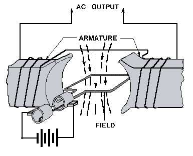
A Generator primarily comprises of two main components "STATOR" and a "ROTOR". A Stator is the stationary part and where as the Rotor is the moving part. In every generator, stator is a single or a set of magnets, while the rotor is a metal loop which rotates in it. When metal loop of a rotor, revolves between the magnets, the magnetic field associated with electrons in them changes and an electric current is generated in it. With every rotation, the changing magnetic field creates a current, which is then transported through a coil to an external electrical circuit. |
| Figure shows a Typical Rotating Armature Generator |
So a today's generator will have an arrangement some what like this:
STATOR - This is the stationary component. It contains a set of electrical conductors wound in coils over an iron core.
ROTOR - Which is also called the Armature. This is the moving component which is creating a rotating Magnetic field. To create this Rotating magnetic field, any of the following ways can be adopted:
 |
| Figure shows a Typical Rotating Field Generator |
- By Induction - Generators which make use of this method are called Brushless Generators. In Brushless Generators DC voltage for magnetic field excitation of rotor is supplied through rotating Bridge Rectifiers which are placed on the rotor.
- By use of Permanent Magnets - This is quite common in small Alternator units. In these units permanent magnets are placed on the rotor. As there are permanent magnets being placed there is no need for excitation.
- By using an Exciter - An Exciter is a small source of direct current which energizes the rotor through an assembly of conducting slip rings and carbon brushes.
Now what's with all this DC supply in a Generator and what is Excitation?
Excitation means producing an electrical magnetic field. To get a constant magnetic field it is necessary that a DC voltage is applied to a coil. Only DC voltage can give a fixed magnetic field and if AC voltage was to be supplied then it will produce a fluctuating magnetic field which in turn will result in a fluctuating voltage.
There are two types of exciters
- STATIC EXCITERS - Static Excitation means no moving parts. It provides faster transient response than rotary exciters. They are of 2 types -
- SHUNT TYPE - power for operating these types of exciters is obtained from generator output voltage
- SERIES TYPE - power for operating these types of exciters is obtained from generator output voltage and current
- ROTARY EXCITERS - They are also of 2 types -
- BRUSHLESS - Do not require slip rings, commutators, brushes and are practically maintenance free.
- BRUSH TYPE - Require slip rings, commutators and brushes and require periodic maintenance.
The current collecting assembly in a generator comprises of brushes and slip rings.
So what are they?
A slip ring is a method of making an electrical connection to a rotating assembly. In a way we can say that its like a rotating coupling which is making connection to a rotating assembly to an external circuit or vice versa. A brush is what pushes against this coupling and provides as a medium of making this connection.
Figure below gives a clearer picture of how brushes and slip rings are connected.

At this point of discussion it would be wise to introduce the term AC generator and DC generator.
So what's an AC Generator and a DC generator?
Well, the answer is simple. AC generators are what produce Alternating current and DC generators are what produce Direct Current. From design point of view it is the Slip Rings which enable us to distinguish between the two. DC generators make use of Split Rings which are also known as Commutator.
In A.C. generator, it is the brushed run on slip rings which maintain a constant connection between the rotating coil and the external circuit. It means that as the induced EMF changes polarity (simply mean +ve or -ve) with every half-turn of the coil, the voltage in the external circuit varies like a sine wave and the current alternates the direction.
In a D.C generator the split ring commutator reverses the flow of current every half turn and as a result what we get is a unidirectional flow of charge.
 |
| A simple picture illustrating the design difference between AC and DC generators |
The figure below shows AC and DC wave forms.

GENERATORS OR ALTERNATORS, WHAT'S YOUR PICK?
Having understood the working of a generator it is quite essential for us to understand where do we have to use the term GENERATOR or ALTERNATOR? Are the two terms same? If no, what's the difference between the two?
Generators and Alternators are quite different from each other and quite often we get confused and don't know where to use which term. The main difference between an alternator and a generator is about its construction i.e what spins inside and what's stationary. In an alternator it is the magnetic field which spins inside the stator which is a windings of wire. In a generator, on the other hand it is the armature or windings of wire spins inside a fixed magnetic field. The alternator can spin at much higher speeds, so it produces more power both at idle and at higher speeds. Alternators convert AC into DC current more easily, too, using solid state diodes.
So on board our ships what do we have is Generator or Alternator?
On board our ships we use ALTERNATORS which is driven by a Diesel Engine.
P.S. In this topic I have used the word Generators and not Alternators only to give a clearer understanding. Always remember that Both Generators and Alternators convert Mechanical energy to Electrical energy.
Having understood the principle components of a Generator in this post, we will get into circuit diagrams, power, and other generator related concepts in the forthcoming posts.
Your explanation are simple to understand 🙏
ReplyDelete