Wednesday 2 January 2013

WHAT MEASURES WHAT?


Now that we are aware of the 4 terms (VOLTAGE, CURRENT, POWER, FREQUENCY) which associated with electricity, lets take a look at what all instruments we need to measure them and how they work.

If you want to measure VOLTAGE we use an instrument called VOLTMETER
If you want to measure CURRENT we use an instrument called AMMETER
If you want to measure POWER we use an instrument called WATTMETER
If you want to measure FREQUENCY we use an instrument called FREQUENCY METER

Lets now briefly take a look at how these instruments work:

VOLTMETER

Figure shows a typical Voltmeter
The basic analog voltmeter comprises of a 'pointer' needle which is attached to a movable coil which in turn is mounted on a pivot. The pivot allows the coil to rotate, which lets the pointer swing across the meter face marked with a graduated scale., The coil is situated between two opposing polarity magnets. The coil is also spring loaded so as to keep the needle at zero when no voltage is supplied.When a voltage is applied to the coil, the coil starts to rotate against the spring. As more voltage is applied, more force is generated between the coil and the magnets causing the coil to rotate further. As the coil rotates, the needle moves across the meter face and the voltage can be read from the scale on the meter face. 


Image showing working of a analog voltmeter


AMMETER 

The basic analog ammeter comprises of a 'pointer' needle which is attached to a movable coil which in turn is mounted on a pivot. The pivot allows the coil to rotate, which lets the pointer swing across the meter face marked with a graduated scale., The coil is situated between two opposing polarity magnets. The coil is also spring loaded so as to keep the needle at zero when no current is supplied.When a current is applied to the coil, the coil starts to rotate against the spring. As more current is applied, more force is generated between the coil and the magnets causing the coil to rotate further. As the coil rotates, the needle moves across the meter face and the current can be read from the scale on the meter face.


It looks exactly the same as a voltmeter?
Yes both work on the same principle and their construction is the same however the only difference between the two instruments is the way in which resistors are used, within the instruments, to make one suitable for measuring current and the other suitable for measuring voltage. Always remember that in voltmeters the current which operates the coil is proportional to the voltage appearing across the voltage. 

Please note that when we measure voltage, voltmeter, it is connected in parallel to the circuit under test and when measuring current, ammeter, is connected in series to the circuit under test.

WATTMETER

A wattmeter comprises of three coils out of which two are fixed coils which are connected in series with the electrical load, and a moving coil which is called the potential coil in parallel with it. The coil connected in series measure the current flowing through the circuit where as the the parallel coil measures the voltage. Potential coil has a resistor connected in series to it and it carries a needle which moves over a suitably marked scale.  The magnetic field in all the three coils influence the needle movement.  A spring is connected to the needle which holds the needle to zero position when no current or voltage are present.

Image take from tpub
 
FREQUENCY METER


Every physical object (which possess the property of elasticity) has a certain inherent frequency at which it vibrates and this is called Resonant Frequency. The tuning fork is a great example of this: strike it once and it will continue to vibrate at a tone specific to its length.
Imagine a row of progressively-sized tuning forks which arranged side-by-side and  are all mounted on a common base, and that base is vibrated at the frequency of the measured AC voltage (or current) by means of an electromagnet. Whichever tuning fork is closest in resonant frequency to the frequency of that vibration will tend to shake the most and can be seen shaking on the meter.  
Vibrating reed frequency diagram - Image source - all about circuits
Image showing the front view of the Vibrating reed frequency meter - Image source all about circuits


Wednesday 19 December 2012

UNDERSTANDING THE CONCEPT OF FREQUENCY


Frequency like power is term which we use in our day to day life and has different meanings in physics, maths, statistics, etc.  Once again we are more interested in what Frequency means in electricity.  So to do we must first understand the general meaning of frequency, then the meaning of frequency in physics and eventually in electricity.

If we were to look up the meaning of the word frequency in a dictionary we would find the meaning as
"the number of times that an event occurs in a given period ; rate of recurrence"

In physics Frequency would mean " the number of periodic oscillations, vibrations, or waves occurring per unit time" or in simple terms "frequency is reciprocal of time period" or "number of cycles per unit time".  Frequency is represented as f=1/T, where f=frequency, T=time period.  SI unit of frequency os HERTZ (Hz).  1Hz means that an event repeats every one second.

To understand frequency let's first of all take a look at a wave and its terminology.


When it comes to waves, frequency is inversely proportional to wave length which is denoted by the symbol lambda (λ).  Therefore we have

f  is proportional to 1/λ. or f=v/λ, where f=frequency, v=velocity of the wave, λ= wavelength

There are different kind of waves but the most common types are Electromagnetic waves like light and radio waves and mechanical waves like sound and seismic waves.

FREQUENCY IN ELECTRICITY, what does it mean?
Well the answer is simple, frequency simply means "how many times an alternating voltage will change its direction in one second"?  

So in simple terms in electricity, frequency simply means "number of cycles per unit time".  f=1/T, where f=frequency, T=time period.

Always remember, One cycle simply means one crest and trough in a sine wave.

Figure explains meaning of one complete cycle.

Figure explains the meaning of period

Lets define frequency now in a proper manner in electricity


In electricity, one cycle is defined as the time it takes for the voltage to start at zero then reach maximum voltage in positive, then again come back to zero, then reach maximum voltage in negative and then eventually again come back to zero.  Now frequency is the number of times this cycle occurs in one second.  For e.g. if we say 10 Hz, then it means there are 10 cycles occurring in one second


Having learnt the meaning of frequency lets find out how to calculate frequency.

So how is frequency determined?

Frequency of an AC generator is determined by using the following two ways:

  1. The speed at which the rotor turns in a magnetic field
  2. The number of stator poles that create the magnetic field through which the rotor turns
Faster the rotor turns in a stator, it produces an AC voltage at a greater frequency as compared to a rotor turning at a slower speed.  Greater the number of poles in an AC generator greater is the frequency.  If we were to assume that the rotor is turning at the same speed, than the frequency of a 4 pole generator is twice that of a 2 pole generator.

In order to calculate frequency, the following formula is used

f=PN/60, where f=Frequency, P= Number of pairs of stator poles, N= is the rotational speed of rotor in rpm, 60=formula constant for converting minutes to seconds.

What's with 50Hz and 60Hz? 

Well the answer is simple, 50Hz simply means voltage alternates 50 times per second and 60 Hz simply means voltage alternates 60 times per second.  50Hz is what we get in most of Europe and Asian countries including India, where as 60Hz is the normal frequency for Americas.  

So,if you are traveling abroad its always better to know what's the voltage and frequency supplies in that particular country.  Click on this link  and get your self prepared to charge your gadgets.

What's the frequency used on board our ships?

On board our ships it is 60Hz.  

The next question that comes is why 60Hz even though half the world is using 50 Hz?
Well to this, answer is simple, The higher frequency means that generators and motors run at higher speeds with a consequent reduction in physical size of machinery for a given power rating. A reduction in size of the machinery is a very important issue when it comes to ship designing, as we all know ships are made to make money so lesser the size of any machinery greater the possibility to increase the cargo carrying capacity and hence make more money! 

So what happens if we have high frequency or low frequency?

Lets put the question in this way "What will happen if we connect a 60 Hz appliance to 50 Hz supply?  
P.S. The consequences entirely depends on the type of appliance connected, but we are more interested in ship board appliances especially Electric Motors, so we will answer this question taking into consideration the consequences that will occur with respect to motor.
Answer - If we were to connect 60 Hz motor to a 50Hz supply then Motor would work, but it will run at a lower speed.  This would simply mean that the work a motor is doing e.g driving a pump will be reduced and the pump will run at a lower speed.  This will eventually have an effect on systems where flow rate is important.  Apart from running slow, motor will draw more current than what it is designed for and as a result will cause overheating of motor, which may eventually cause fire or a burn out of motor.

So next question here is can we really run a motor with 60Hz frequency run on a 50 Hz supply?

Well to this the answer is yes, Motor will run at a lower RPM and to avoid that overheating problem it is important to reduce the voltage.  Always take into consideration the Voltage/Frequency ratio.  Voltage/frequency ratio is always constant for e.g. 440/60 HZ = 7.33, Now taking 7.33 as constant and we have to connect a motor with a frequency of 50Hz the voltage should now kept at:-
Voltage/50=7.33, This would mean , Voltage = 50*7.33=366.5 Volts.

and what will happen if we connect a 50 Hz Motor to a 60 Hz supply?

The next scenario is connecting a 50 Hz motor to a 60 Hz supply.  If we were to this than motor will run faster.  This would simply mean that the work a motor is doing e.g. driving a pump will be increased and the pump will run at a higher speed.  This will eventually have an effect on the system where flow rate is important and can also damage the system (like damage to pipelines) due to increased flow rate.  Also there is a possibility that the pump may get damaged due to increased rpm.  Also increase in rpm would simply mean that the motor will overload and as a result pump will not be able to run at higher loads.

So next question here is can we really run a motor with 50 Hz frequency on a 60 Hz supply?

Well to this answer is yes.  Motor will run at a higher RPM and to avoid it from getting overloaded run the pump at a lower capacity.  

Also always remember DC voltage has no frequency as the voltage of the DC supply does not change and hence it does not cycle like AC supply.

Saturday 15 December 2012

UNDERSTANDING THE CONCEPT OF POWER


Power is a term which am sure we use in our day to day life and term has different meanings in Politics, Physics, Maths, etc.  We are more interested here in what power means in Electricity.  So to do that we must first of all understand the general meaning of power, in physics and eventually in Electricity.

If we were to look up the meaning of the word Power in a Dictionary we would find the meaning as
" the ability to do or act; capability of doing something or accomplishing something".

In physics power would mean "the rate at which energy is transformed, used, or transferred".  We can represent power as P=W/T OR P=E/T,  here P=Power, W=Work, E=Energy and T=Time.  So as far as SI units is concerned units for power is Joules which is for energy per unit time in seconds.  So P=Joules/Second.  This is what is known as WATTS. So Unit of Power is Watt.  Watt can also be represented as Kilowatts(KW), Megawatts(MW), etc.  1KW=1000 watts and 1MW = 1000,000 watts.

Now in terms of electricity we would define Power as "
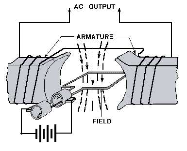
the rate at which electric energy is transferred in an electrical circuit".  As explained in my previous post it is Generators which produce this power.  The SI unit of power in terms of electricity remain the same as that in physics which is Watts.

In my previous post i have explained the meaning of current and voltage in terms of cause and effect.  We must always remember that current is a measure of moving electrons or charge per unit time and voltage is what makes these electrons move.

Now what has Power got to do with all this?
Answer to this question will be Power has got everything to do with all this.  It is actually voltage and current which makes Power.
In electricity P=VI, i.e. Power is voltage multiplied by current.
Now at this point is becomes very important for us to once again go back to school and recall all about Inductors ,Capacitors and Resistors.


BACK TO SCHOOL
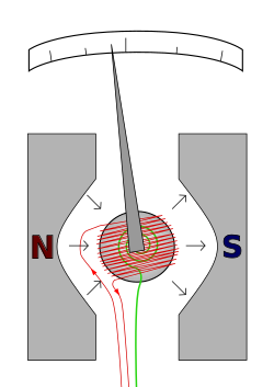
INDUCTORS -  Inductor in simple terms is simply a coil of wire.  As current is made to pass through this coil of wire it produces a magnetic field which is responsible for storing energy.  Let's take a very simple example, if we were to put an inductor in a simple electric bulb circuit then the bulb would stay lit till the magnetic field around the inductor dies out, which is making the flow of current to still persist even after switching off the current i.e simply switch off the switch. Inductance is a term which is used to define that phenomenon whereby an EMF is generated in a closed circuit due to change of flow of current which occurs by placing a coil in the circuit. Inductance is directly proportional to the number of turns in the coil.   Inductance also depends on the radius of the coil and also on the type of material around which coil is wound.
The SI unit for measuring Inductance is HENRY.

CAPACITORS - A capacitor comprises of 2 conductors which are separated by a dielectric material of uniform thickness.  Dielectric material is usually an insulator.  A capacitor is something which stores energy in an electrical field and releases it in the electrical when required. Capacitance is a term which is used to define how much charge a capacitor can hold.  The amount of charge a capacitor can hold depends on the amount of  voltage that is applied.  If we double the voltage than a capacitor can hold twice the charge.  Capacitance in simple terms can also be said charge per volt a capacitor can hold.  SI unit for capacitance is FARAD(F).  Therefore Capacitance is given by C=Q/V, where C=Capacitance, Q=Charge, V=Voltage difference between capacitor plates.

RESISTORS -As the name suggests an resistor is an electronic component which resists the flow of current in an electric circuit. A Resistor is responsible for maintaining a constant relation between Voltage and Current.  Resistors usually decrease the voltage and as a result decrease the current in an electric circuit.  The amount of electric current which is absorbed in a resistor is called Resistance and the SI unit is OHMS.
Relation between voltage, current and resistance is given by ohms law which states R=V/I.  Where R=Resistance, V=Voltage, I=Current.

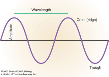
In my last post we have learnt about AC and DC wave forms.  (Please note that we are mainly interested in AC wave forms).  Voltage and current in an AC circuit are sinusoidal in nature.  This means that the amplitude of voltage and current changes over time.  Now that we have learnt that power is equal to product of voltage and current, and therefore as a result power is maximized when voltage and current are lined up with one another i.e peaks and the zero points on the wave form are lined up with one another.


Figure shows voltage and current sinusoidal waveform
 Now as the figure above shows, in such a situation Voltage and Current are said to be in phase with one another.  Two waveforms apart from being in phase with one another can be OUT OF PHASE or PHASE SHIFTED when current and voltage do not match from point to point.

So what makes this phase shift?
It is Resistors, Conductors and Inductors which are responsible for this change of phase.  Each of these components have a different effect of the phase shift between voltage and current.
Let's now take a look at the effect of each component on voltage and current waveform.
  1. RESISTOR - A resistor causes no shift between current and voltage waveform.


 Power that is resultant of a purely resistive load is called TRUE POWER.  It is actually this power from generators that is responsible for driving our motors on board or will drive a circuit.  This power is measured in Watts (W).  In a way we can say that True Power is the desired outcome of an electrical system.
Recalling what we have stated earlier, P=VI and as per ohms law we now know that R=V/I or V=RI or I=V/R.  Now combing these two equations we will get.
P=I^2R or P=V^2/R (I square or V square), this is what is True Power.

2. CAPACITOR AND INDUCTOR - A capacitor or an inductor will cause a 90 degree phase shift between voltage and current.  The resulting power will have a value of ZERO every time current or voltage reaches a zero value as Power is the product of Voltage and Current.  As the value of power is zero it simply means that even though power is being generated still no work is being done.  This type of Power is called REACTIVE POWER.  True power is actually doing all the work while reactive power is taking away from power and as a result making True power to work more to get the job done.  Reactive power is measure as REACTIVE VOLT-AMPS (VAr).

A capacitor in an AC circuit will cause the voltage to LAG current by a phase angle of 90 degrees and as result will introduce a Negative reactive power.


An Inductor in an AC circuit will cause the voltage to LEAD current by a phase angle of 90 degrees and as a result will introduce a Positive Reactive Power.


We can also say that Capacitors generate reactive power and Inductors consume reactive power.

Having learnt True and Reactive power there is one more Power that we must understand which is called the  COMPLEX POWER/APPARENT POWER.  Complex power is the vector summation of True and Reactive power and Apparent power is the Magnitude of complex power.  Let's now take a look at Power Triangle.  Vector summation is simply determined by the use of  Pythagoras theorem as we have studied in our school days.  Apparent power is measured in Volts.Amps (VA) and so is complex power.

Now here as S is the Apparent power, Q is the reactive power, P is the total power

Therefore S= Sq. root of Q^2 + P^2

Let's recall what we have learnt so far

P= True power that performs work measure in (W) Watts.
Q= Power that does not perform work (sometimes called wattless power) measured in VAr (volta amp reactive)
S= Complex power is the vector summation of both True Power and Reactive Power measured in VA(Volt Amps)
/S\ - Apparent power is the magnitude of the complex power measure in VA (Volt Amps)
= Phase Angle.  This is the angle which is used to describe the phase shift between voltage and current. Larger the phase angle greater the reactive power generated in the system

As we have learnt that Apparent power is the vector summation of True power and Reactive power, therefore it simply means that both magnitude of the true and magnitude of the reactive power together with the phase shift between the voltage and current affect the apparent power value.  Apparent power is used to describe the total power delivered to a load.

What is Power Factor?
Ratio between real power and Apparent power is termed as Power Factor.  This ratio represents the Cosine angle in a power triangle.  This means


= REAL POWER/APPARENT POWER

Power factor is the practical measure of the efficiency of a power distribution system.  
Power factor is 1 when the voltage and current are in phase.  This happens only when the load is purely resistive. It is zero when the current leads or lags the voltage by 90 degrees. This happens when the load is inductive or capacitive. So power factor is always in the range of 0 and 1.  Loads with lower power factor are inductive i.e. Power factors is lagging and loads with higher power factor are capacitive i.e power factor is leading. Power factors are usually leading or lagging to show the sign of the phase angle of current with respect to voltage.

 The word lagging or leading simply implies that it is current which is lagging the voltage or leading the voltage.
Alternator sets are usually rated in kVA at 0.8 power factor lagging.  This means that alternators are rated in terms of Apparent Power.  Let's take a simple example of what this 0.8 means here.
If we are said that 1000 kVA is an alternator output than the true power output or Engine power output is=1000 x 0.8 = 80 KW.

Let's now take a look at what happens when we have the following conditions and answer this question, WHY 0.8 POWER FACTOR LAGGING IS CHOSEN?

Effect of power factor on engines kVA when engine is designed for 0.8 lagging

  • if the lagging power factor is less than 0.8 = If we have a power factor LESS than 0.8 there will be heating of the rotor winding at 100% of alternator kVA output. 
  • if leading power factor results, in alternator, stator end iron heating occurs and the alternator automatic voltage control system becomes stable
Effect of power factor on engines KW when engine is designed for 0.8 lagging

  • Lagging power factor is greater than 0.8 = If we have a power factor MORE than 0.8 than engine will not have sufficient KW to power the alternator to 100% of its kVA rating
  • Lagging power factor is smaller than 0.8 = If we have a power factor LESS than 0.8 than than engine will have surplus KW to power the alternator to 100% of its kVA rating
Also please note that a 0.8 power factor is common and relatively inexpensive, however it is possible to design an alternator with any power factor.

At the end of this post i can only say that always remember

  • Apparent power is the combination of both Reactive power and True power.  
  • True power is a result of resistive components
  • Reactive power is a result of capacitive and inductive components
  • It is reactive power which is used to maintain the voltage
  • If reactive power increases the voltage increases and if reactive power lowers voltage reduces


Saturday 8 December 2012

GENERATORS


Picture showing Diesel engines coupled to alternators 


Having learnt about electricity let's now take a look at what generates electricity - "GENERATOR".  A generator is a device which converts mechanical energy into electric energy.
In a Generator a big coil of copper wire spins inside the Magnets ( This spinning is done by Diesel Generator or Prime Mover).  As it spins, the magnetic field made by the magnets push and pull the electrons in the copper wire and as a result generate electricity.  These moving electrons from copper wire flow into the power lines and these moving electrons are what are known as CURRENT.  In other words we can say that Electric Current is a measure of the amount of electrical charge transferred per unit time.  It is represented in Amperes which means coulomb/sec.

HOW DOES A GENERATOR WORK?

As is in my previous post we have learnt that any charge moving through a magnetic field experiences a force.  This force is what is called EMF, Electro Motive Force which is measured in Volts.  In simple terms we can say that the force which makes the electrons move through a conductor is called EMF.  EMF is measured in Volts which is energy per unit charge.  EMF is actually not a force but a  pressure which is moving the electrons.

All the work in relation to EMF was done by FARADAY who proved that "Any change in the magnetic environment of a coil of wire will cause a voltage (emf) to be "induced" in the coil. No matter how the change is produced, the voltage will be generated. The change could be produced by changing the magnetic field strength, moving a magnet toward or away from the coil, moving the coil into or out of the magnetic field, rotating the coil relative to the magnet, etc."
At this point we can say that generators principally work on the fundamentals of Electromagnetic Induction.

Lets watch a video to understand what Electro Magnetic Induction really means


We have now come across the two major terms VOLTAGE and CURRENT.  It is of utmost importance that we understand the difference between the two at this point.


BACK TO SCHOOL

I am sure that we all have seen the movie "MATRIX" and we all have seen the character called "the Merovingian" who is always talking about CAUSE and EFFECT.  Let's apply his concept to life in electricity.

I would say Voltage is the Cause and Current is the Effect.  We are now in a position to say that it is Voltage which makes a Current flow in a closed circuit.  Voltage can exist without current but current can't exist without voltage.  Voltage is measured in volts and current in Amps.  Voltage is measured by an instrument called voltmeter and current by Ammeter.  

So what's inside a Generator?

A generator can have a rotating coil in a Magnetic field or a rotating magnetic field in a stationary coil.
A Generator primarily comprises of two main components "STATOR" and a "ROTOR".  A Stator is the stationary part and where as the Rotor is the moving part. In every generator, stator is a single or a set of magnets, while the rotor is a metal loop which rotates in it. When metal loop of a rotor, revolves between the magnets, the magnetic field associated with electrons in them changes and an electric current is generated in it. With every rotation, the changing magnetic field creates a current, which is then transported through a coil to an external electrical circuit.

Figure shows a Typical Rotating Armature Generator
  

Now a days Generators have an alternative arrangement, where the stator can be the metal loop, while rotor is the magnet. That is a magnet rotates around a stationary metal loop, generating current in it. 
So a today's generator will have an arrangement some what like this:
STATOR - This is the stationary component.  It contains a set of electrical conductors wound in coils over an iron core.
ROTOR - Which is also called the Armature.  This is the moving component which is creating a rotating Magnetic field.  To create this Rotating magnetic field, any of the following ways can be adopted:
Figure shows a Typical Rotating Field Generator
  • By Induction - Generators which make use of this method are called Brushless Generators.  In Brushless Generators DC voltage for magnetic field excitation of rotor is supplied through rotating Bridge Rectifiers which are placed on the rotor.    
  •  By use of Permanent Magnets - This is quite common in small Alternator units.  In these units permanent magnets are placed on the rotor.  As there are permanent magnets being placed there is no need for excitation.
  • By using an Exciter - An Exciter is a small source of direct current which energizes the rotor through an assembly of conducting slip rings and carbon brushes.
Let's watch another video which will give us a clearer understanding of the construction and working of a Generator.  (Please note that I'am not explaining the Flemings left and right hand rules and lenz's law which are explained in this video).


Now what's with all this DC supply in a Generator and what is Excitation?

Excitation means producing an electrical magnetic field.  To get a constant magnetic field it is necessary that a DC voltage is applied to a coil.  Only DC voltage can give a fixed magnetic field and if AC voltage was to be supplied then it will produce a fluctuating magnetic field which in turn will result in a fluctuating voltage. 
There are two types of exciters
  • STATIC EXCITERS - Static Excitation means no moving parts.  It provides faster transient response than rotary exciters.  They are of 2 types - 
  1. SHUNT TYPE - power for operating these types of exciters is obtained from generator output voltage
  2. SERIES TYPE - power for operating these types of exciters is obtained from generator output voltage and current
  •   ROTARY EXCITERS - They are also of 2 types - 
  1. BRUSHLESS - Do not require slip rings, commutators, brushes and are practically maintenance free.
  2. BRUSH TYPE - Require slip rings, commutators and brushes and require periodic maintenance. 


The current collecting assembly in a generator comprises of brushes and slip rings.

So what are they?

A slip ring is a method of making an electrical connection to a rotating assembly.  In a way we can say that its like a rotating coupling which is making connection to a rotating assembly to an external circuit or vice versa.  A brush is what pushes against this coupling and provides as a medium of making this connection.

  Figure below gives a clearer picture of how brushes and slip rings are connected.


At this point of discussion it would be wise to introduce the term AC generator and DC generator.

So what's  an AC Generator and a DC generator?

Well, the answer is simple. AC generators are what produce Alternating current and DC generators are what produce Direct Current.  From design point of view it is the Slip Rings which enable us to distinguish between the two.  DC generators make use of Split Rings which are also known as Commutator.

In A.C. generator, it is the brushed run on slip rings which maintain a constant connection between the rotating coil and the external circuit. It means that as the induced EMF changes polarity (simply mean +ve or -ve) with every half-turn of the coil, the voltage in the external circuit varies like a sine wave and the current alternates the direction.

In a D.C generator the split ring commutator reverses the flow of current every half turn and as a result what we get is a unidirectional flow of charge.

A simple picture illustrating the design difference between AC and DC generators


The figure below shows AC and DC wave forms.


GENERATORS OR ALTERNATORS, WHAT'S YOUR PICK?

Having understood the working of a generator it is quite essential for us to understand where do we have to use the term GENERATOR or ALTERNATOR?  Are the two terms same?  If no, what's the difference between the two?
Generators and Alternators are quite different from each other and quite often we get confused and don't know where to use which term. The main difference between an alternator and a generator is about its construction i.e what spins inside and what's stationary.  In an alternator it is the magnetic field which spins inside the stator which is a windings of wire.  In a generator, on the other hand it is the armature or windings of wire spins inside a fixed magnetic field.  The alternator can spin at much higher speeds, so it produces more power both at idle and at higher speeds. Alternators convert AC into DC current more easily, too, using solid state diodes. 

So on board our ships what do we have is Generator or Alternator?
On board our ships we use ALTERNATORS which is driven by a Diesel Engine.


P.S. In this topic I have used the word Generators and not Alternators only to give a clearer understanding.  Always remember that Both Generators and Alternators convert Mechanical energy to Electrical energy.

Having understood the principle components of a Generator in this post, we will get into circuit diagrams, power, and other generator related concepts in the forthcoming posts.  


Friday 7 December 2012

UNDERSTANDING THE TERM "ELECTRICITY"


ELECTRICITY

Dow we really know what electricity means?  We all know one thing for sure, if we have a power cut at our home which is quite common in india, we just can't do anything starting from watching TV to taking a hot water bath or perhaps grind something to make that lovely meal.  A Power cut at home is still bearable but a power loss at sea!!! Don't want to write the consequences......we all know what will happen.....
We know we are totally dependent on it and we have hooked up almost every appliance on earth to "Electricity".
In this first post I have tried to explain the meaning of the word Electricity as it get very difficult to get further in the topic without knowing how it works.

This section is entirely "BACK TO SCHOOL"


Origin of the word Electricity

  Word electricity originated from Greek word - "ELEKTOR" which means beaming sun. Electricity is all about Protons, Neutrons, Electrons, Atoms. Let's have a look on everything that makes electricity work.

What is Electricity after all?

We all know that the earth revolves around the sun and so do other planets of our solar system and like this there are many other solar systems that combine to form what is called universe.  However universe is a combination of not only solar systems but many other things as well.
Now i say that the universe is something that surrounds our planet and other stars.  In the similar fashion there is another nano universe that surrounds us which we can't see.  Thats a universe of atoms, protons, neutrons, electrons.

We all know that matter is something that has weight and occupies space.  It is atoms that make matter i.e. atoms are the building blocks of matter.  Atoms are made up of even more smaller particles.  The three main particles which are making an atom are Protons, Neutrons and Electrons. . Just the way earth spins around the sun,similarly Electrons spin around the Nucleus, which is made up of Protons and Neutrons  In an atom, Protons are positively charged, Electrons are negatively charged and Neutrons are neutral. 

Atoms are Building blocks of matter and Elements too are building blocks of matter i.e. it is elements that make matter.  In a way we can say that an Atom is a single part that makes up an Element.  There are 118 different types of elements known so far of which oxygen is one.

Each atom has a certain number of electrons, protons and neutrons.  These protons and electrons always try to balance out each other i.e. the number of protons try to be the same number of electrons and as a result atom is said to be balanced or stable. 

Some atoms have loosely attached electrons.  An atom which looses electrons will have more protons than electrons and as a result will be positively charged and is called cation and on the contrary an atom which gains electrons will have a negative charge and is called anion.  So a charged atom is called "ion".

When these electrons move from one atom to another then a current of Electricity is created.  So in simple terms we can say Electricity is Moving electrons.

So what is meant by Conductors and Insulators?

It's simple, things which allow the moving electrons to flow through them are Conductors and things which restrict the flow of electrons is called Insulators.  Examples of good conductors - Gold, Copper, Aluminum, etc whereas Rubber, Plastic, Cloth, Glass are good examples of Insulators.  

So who makes Electrons Move?


 Answer is Simple, MAGNETS.  Magnets have atoms in which electrons are unbalanced unlike any other object where atoms are balanced.  In a magnet half the electrons spin in one direction and half in another as can be seen in the animation.  In magnets the most special thing is that electrons are not moving to find balance and this creates a force of energy which is called Magnetic Field around the magnet.
This Magnetic field can now be made to push and pull electrons and make them move.  Some metals i.e. good conductors like copper which have loosely held electrons can be easily pushed.

Magnetism and electricity and closely lined to each other.  Magnets create Electricity and Electricity creates Magnetic fields.  A Generator is a fine example of Magnets creating Electricity and a Motor is a fine example of Electricity creating Magnetic fields.
Magnetism and electricity are inseparably linked to each other . Where there is magnetism there is electricity or vice-versa and this is called ELECTROMAGNETISM.

So we know now what is electricity and how it is generated.  Next post will go further in the topic and understand the working of Generators and Electric Motors.